
Datasheet


Section 7 I/O Ports
Rev. 2.00 Sep. 28, 2009 Page 167 of 994
REJ09B0452-0200
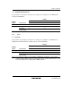
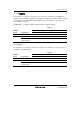
(2) P96/φ/EXCL
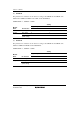
The pin function is switched as shown below according to the combination of the register settings
of the EXCLS bit in PTCNT0, EXCLE bit in LPWRCR, and the P96DDR bit.
Setting
I/O Port
Module
Name
Pin Function
P96DDR
Clock φ output
1
I/O port P96 input
(initial setting)
0
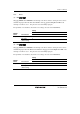
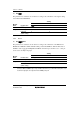
(3) P95/IRQ14, P94/IRQ13, P93/IRQ12, P92/IRQ0, P91/IRQ1, P90/IRQ2
The pin function is switched as shown below according to the state of the P9nDDR bit. When the
ISSm bit in ISSR (ISSR16) is cleared to 0 and the IRQmE bit in IER (IER16) of the interrupt
controller is set to 1, this pin can be used as the IRQm input pin.
Setting
I/O Port
Module
Name
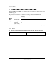
Pin Function P9nDDR
I/O port P9n output 1
P9n input
(initial setting)
0
(n = 5 to 0)
(m = 14 to 12, 2 to 0)