
Datasheet

Section 10 16-Bit Timer Pulse Unit (TPU)
Rev. 2.00 Sep. 28, 2009 Page 260 of 994
REJ09B0452-0200
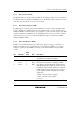
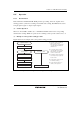
10.3.5 Timer Status Register (TSR)
The TSR registers indicate the status of each channel. The TPU has three TSR registers, one for
each channel.
Bit Bit Name
Initial
value
R/W Description
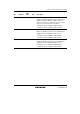
7 TCFD 1 R Count Direction Flag
Status flag that shows the direction in which TCNT
counts in channel 1 and 2. In channel 0, bit 7 is
reserved. It is always read as 0 and cannot be modified.
0: TCNT counts down
1: TCNT counts up
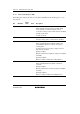
6 ⎯ 1 R Reserved
This bit is always read as 1 and cannot be modified.
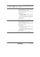
5 TCFU 0 R/(W)* Underflow Flag
Status flag that indicates that TCNT underflow has
occurred when channels 1 and 2 are set to phase
counting mode.
In channel 0, bit 5 is reserved. It is always read as 0
and cannot be modified.
[Setting condition]
When the TCNT value underflows (change from H'0000
to H'FFFF)
[Clearing condition]
When 0 is written to TCFU after reading TCFU = 1
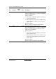
4 TCFV 0 R/(W) * Overflow Flag
Status flag that indicates that TCNT overflow has
occurred.
[Setting condition]
When the TCNT value overflows (change from H'FFFF
to H'0000)
[Clearing condition]
When 0 is written to TCFV after reading TCFV = 1