
Datasheet

Section 12 16-Bit Duty Period Measurement Timer (TDP)
Rev. 2.00 Sep. 28, 2009 Page 339 of 994
REJ09B0452-0200
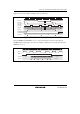
Bit Bit Name
Initial
Value
R/W Description
4 IEDG 0 R/W Input Edge Select
In timer mode, in combination with the value of the POCTL
bit, selects the falling or rising edge of the TDPCYI input for
capturing input.
In cycle measurement mode, this bit does not affect
operation.
When POCTL = 0
0: The falling edge of TDPCYI input is selected
1: The rising edge of TDPCYI input is selected
When POCTL = 1
0: The rising edge of TDPCYI input is selected
1: The falling edge of TDPCYI input is selected
3 TDPMDS 0 R/W TDP Mode Select
Selects the TDP operating mode.
0: Timer mode
In timer mode, the operating mode is input capture and
compare match.
1: Cycle measurement mode
Setting this bit to 1 starts counting by TDPCNT. Clear the
CST bit in TDPCR1 to initialize TDPCNT to H'0000
before setting cycle measurement mode.
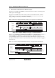
2
1
0
CKS2
CKS1
CKS0
0
0
0
R/W
R/W
R/W
Clock Select 2, 1, 0
These bits select the clock signal for input to TDPCNT. Do
not select the external clock in level control measurement
mode.
000: Counts the φ internal clock
001: Counts the φ/2 internal clock
010: Counts the φ/4 internal clock
011: Counts the φ/8 internal clock
100: Counts the φ/16 internal clock
101: Counts the φ/32 internal clock
110: Counts the φ/64 internal clock
111: Counts the external clock
(Select the external clock edge with CKSEG in TDPCSR.)
Note: Change this bit when CST = 0 and TDPMDS = 0.