
Datasheet

Section 12 16-Bit Duty Period Measurement Timer (TDP)
Rev. 2.00 Sep. 28, 2009 Page 345 of 994
REJ09B0452-0200
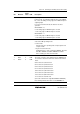
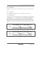
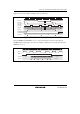
(3) CMF Setting Timing when a Compare Match Occurs
The CMF flag in TDPCSR is set in the last state in which the values in TDPCNT and TDPWDMX
match (timing when TDPCNT updates the matched count value) in timer mode. Accordingly, a
compare match signal is not generated until an additional cycle of the TDPCNT input clock is
generated after a match between the values in TDPCNT and TDPWDMX. For details, see section
12.6.2, Conflict between TDPPDMX Write and Compare Match. Figure 12.6 shows the timing on
which the CMF flag is set.
φ
TDPCNT
TDPWDMX
CMF
N + 1N
N
Compare match
signal
Figure 12.6 Timing of CMF Flag Setting on Compare Match
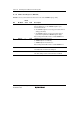
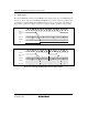
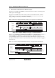
12.4.2 Cycle Measurement Mode
The TDP operates in cycle measurement mode when the TDPMDS bit in TDPCR1 is set to 1.
(1) Counter Operation
TDPCNT counts up in cycle measurement mode regardless of the setting of the CST bit in
TDPCR1. TDPCNT is cleared to H'0000 when the first edge in the measurement period is
detected, from which state it counts up. Figure 12.7 shows an example of counter operation in
cycle measurement mode.
φ
TDPCYI
TDPCNT
clear signal
TDPCNT
input clock
H'0001H'0000 H'0001 H'0002 H'0000H'0003N
TDPCNT
Figure 12.7 Example of Counter Operation in Cycle Measurement Mode