
Datasheet

Section 18 I
2
C Bus Interface (IIC)
Rev. 2.00 Sep. 28, 2009 Page 550 of 994
REJ09B0452-0200
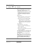
Table 18.6 Flags and Transfer States (Slave Mode)
MST TRS BBSY ESTP STOP IRTR AASX AL AAS ADZ ACKB ICDRF ICDRE State
0 0 0 0 0 0 0 0 0 0 0 — 0 Idle state (flag clearing
required)
0 0 1↑ 0 0 0 0↓ 0 0 0 0 — 1↑ Start condition detected
0 1↑/0
*
1
1 0 0 0 0 — 1↑ 0 0 1↑ 1 SAR match in first frame
(SARX≠SAR)
0 0 1 0 0 0 0 — 1↑ 1↑ 0 1↑ 1 General call address match in
first frame (SARX≠H'00)
0 1↑/0
*
1
1 0 0 1↑ 1↑ — 0 0 0 1↑ 1 SAR match in first frame
(SAR≠SARX)
0 1 1 0 0 — — — — 0 1↑ — — Transmission end (ACKE=1
and ACKB=1)
0 1 1 0 0 1↑/0
*
2
— — — 0 0 — 1↑ Transmission end with
ICDRE=0
0 1 1 0 0 — — 0↓ 0↓ 0 0 — 0↓ ICDR write with the above
state
0 1 1 0 0 — — — — 1 0 1 Transmission end with
ICDRE=1
0 1 1 0 0 — — 0↓ 0↓ 0 0 0↓ ICDR write with the above
state
0 1 1 0 0 1↑/0
*
2
— 0 0 0 0 1↑ Automatic data transfer from
ICDRT to ICDRS with the
above state
0 0 1 0 0 1↑/0
*
2
— — — — — 1↑ — Reception end with ICDRF=0
0 0 1 0 0 — — 0↓ 0↓ 0↓ — 0↓ — ICDR read with the above
state
0 0 1 0 0 — — — — — — 1 — Reception end with ICDRF=1
0 0 1 0 0 — — 0↓ 0↓ 0↓ — 0↓ — ICDR read with the above
state
0 0 1 0 0 1↑/0
*
2
— 0 0 0 — 1↑ — Automatic data transfer from
ICDRS to ICDRR with the
above state
0 — 0↓ 1↑/0
*
3
0/1↑
*
3
— — — — — — — 0↓ Stop condition detected
[Legend]
0: 0-state retained
1: 1-state retained
—: Previous state retained
0
↓: Cleared to 0
1
↑: Set to 1
Notes: 1. Set to 1 when 1 is received as a R/W bit following an address.
2. Set to 1 when the AASX bit is set to 1.
3. When ESTP=1, STOP is 0, or when STOP=1, ESTP is 0.