
Datasheet


Section 18 I
2
C Bus Interface (IIC)
Rev. 2.00 Sep. 28, 2009 Page 561 of 994
REJ09B0452-0200
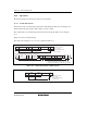
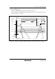
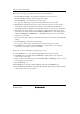
SDA
SCL
S SLA R/W A
981–7 981–7 981–7
DATA A DATA A/A
P
Figure 18.5 I
2
C Bus Timing
Table 18.7 I
2
C Bus Data Format Symbols
Legend
S Start condition. The master device drives SDA from high to low while SCL is high
SLA Slave address. The master device selects the slave device.
R/W Indicates the direction of data transfer: from the slave device to the master device
when R/W is 1, or from the master device to the slave device when R/W is 0
A Acknowledge. The receiving device drives SDA low to acknowledge a transfer. (The
slave device returns acknowledge in master transmit mode, and the master device
returns acknowledge in master receive mode.)
DATA Transferred data. The bit length of transferred data is set with the BC2 to BC0 bits in
ICMR. The MSB first or LSB first is switched with the MLS bit in ICMR.
P Stop condition. The master device drives SDA from low to high while SCL is high