
Datasheet


Section 18 I
2
C Bus Interface (IIC)
Rev. 2.00 Sep. 28, 2009 Page 565 of 994
REJ09B0452-0200
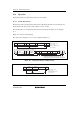
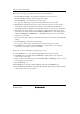
12. Clear the IRIC flag to 0.
Write 0 to ACKE in ICCR, to clear received ACKB contents to 0.
Write 0 to BBSY and SCP in ICCR. This changes SDA from low to high when SCL is high,
and generates the stop condition.
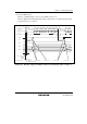
SDA
(master output)
SDA
(slave output)
21
R/W
436587
12
9
A
Bit 7 Bit 6 Bit 5 Bit 4 Bit 3 Bit 2 Bit 1 Bit 0
Bit 7 Bit 6
ICDRE
IRTR
ICDRT
Note:* Data write
in ICDR
prohibited
SCL
(master output)
Start condition generation
Slave address
Data 1
Data 1
[9] ICDR write
[9] IRIC clear
[6] ICDR write
[6] IRIC clear
[4] BBSY set to 1
SCP cleared to 0
(start condition issuance)
User processing
Interrupt
request
Interrupt
request
Address + R/W
IRIC
[7]
[5]
ICDRS
Data 1
Address + R/W
Figure 18.8 Example of Operation Timing in Master Transmit Mode (MLS = WAIT = 0)