
Datasheet


Section 22 A/D Converter
Rev. 2.00 Sep. 28, 2009 Page 732 of 994
REJ09B0452-0200
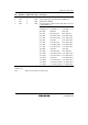
22.3.2 A/D Control/Status Register (ADCSR)
ADCSR controls A/D converter operation.
Bit Bit Name Initial Value R/W Description
7 ADF 0 R/(W)* A/D End Flag
A status flag that indicates the end of A/D conversion.
[Setting conditions]
• When A/D conversion ends in single mode
• When A/D conversion ends on all channels specified
in scan mode
[Clearing condition]
When 0 is written after reading ADF = 1
6 ADIE 0 R/W A/D Interrupt Enable
Enables ADI interrupt by ADF when this bit is set to 1.
5 ADST 0 R/W A/D Start
When this bit is cleared to 0, A/D conversion stops and
enters wait state. When this bit is set to 1 by a conversion
start trigger from software, TPU, or TMR, A/D conversion
starts. This bit remains set to 1 during A/D conversion. In
single mode, this bit is automatically cleared to 0 when
conversion on the specified channel ends. In scan mode,
conversion continues sequentially on the specified
channels until this bit is cleared to 0 by a reset, or
software.
4 ⎯ 0 ⎯ Reserved
This bit is always read as 0 and cannot be modified.