
Datasheet


Section 24 Flash Memory
Rev. 2.00 Sep. 28, 2009 Page 785 of 994
REJ09B0452-0200
7. The return value in the initialization program, the FPFR parameter is determined.
8. All interrupts and the use of a bus master other than the CPU are disabled during
programming/erasing. The specified voltage is applied for the specified time when
programming or erasing. If interrupts occur or the bus mastership is moved to other than the
CPU during programming/erasing, causing a voltage exceeding the specifications to be
applied, the flash memory may be damaged. Therefore, interrupts are disabled by setting bit 7
(I bit) in the condition code register (CCR) to B'1 in interrupt control mode 0 and by setting
bits 2 to 0 (I2 to I0 bits) in the extend register (EXR) to B'111 in interrupt control mode 2.
Accordingly, interrupts other than NMI are held and not executed. Configure the user system
so that NMI interrupts do not occur. The interrupts that are held must be executed after all
programming completes.
9. FKEY must be set to H'5A and the user MAT must be prepared for programming.
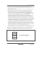
10. The parameters required for programming are set. The start address of the programming
destination on the user MAT (FMPAR parameter) is set in general register ER1. The start
address of the program data storage area (FMPDR parameter) is set in general register ER0.
⎯ Example of FMPAR parameter setting: When an address other than one in the user MAT
area is specified for the start address of the programming destination, even if the
programming program is executed, programming is not executed and an error is returned to
the FPFR parameter. Since the program data for one programming operation is 128 bytes,
the lower eight bits of the address must be H'00 or H'80 to be aligned with the 128-byte
boundary.
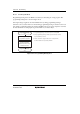
⎯ Example of FMPDR parameter setting: When the storage destination for the program data
is flash memory, even if the programming routine is executed, programming is not
executed and an error is returned to the FPFR parameter. In this case, the program data
must be transferred to the on-chip RAM and then programming must be executed.
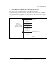
11. Programming is executed. The entry point of the programming program is at the address which
is 16 bytes after #DLTOP (start address of the download destination specified by FTDAR).
Call the subroutine to execute programming by using the following steps.
MOV.L #DLTOP+16,ER2 ; Set entry address to ER2
JSR @ER2 ; Call programming routine
NOP
⎯ The general registers other than R0L are held in the programming program.
⎯ R0L is a return value of the FPFR parameter.
⎯ Since the stack area is used in the programming program, a stack area of 128 bytes at the
maximum must be allocated in RAM.