
Datasheet


Section 25 Clock Pulse Generator
Rev. 2.00 Sep. 28, 2009 Page 839 of 994
REJ09B0452-0200
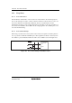
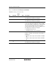
t
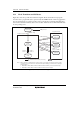
EXCLH
t
EXCLL
t
EXCLr
t
EXCLf
V
CC
× 0.5
EXCL
Figure 25.8 Subclock Input Timing
25.4 Subclock Waveform Forming Circuit
To remove noise from the subclock input at the EXCL (ExEXCL) pin, the subclock waveform
forming circuit samples the subclock using a divided φ clock. The sampling frequency is set by the
NESEL bit in LPWRCR.
The subclock is not sampled in watch mode.
25.5 Clock Select Circuit
The clock select circuit selects the system clock that is used in this LSI.
A clock generated by the oscillator to which the XTAL and EXTAL pins are connected is selected
as a system clock (φ) when returning from high-speed mode, sleep mode, the reset state, or
standby mode.
In watch mode, a subclock input from the EXCL (ExEXCL) pin is selected as a system clock
when the EXCLE bit in LPWRCR is 1. At this time, on-chip peripheral modules such as WDT_1
and interrupt controller operate on the φSUB clock. The count clock and sampling clock for each
timer are divided φSUB clocks.