
Datasheet


Section 5 Interrupt Controller
Rev. 3.00 Sep. 28, 2009 Page 107 of 910
REJ09B0350-0300
⎯ When using the IRQ6 pin as the IRQ6 interrupt input pin, the KMIMR6 bit must be cleared
to 0. When using the IRQ7 pin as the IRQ7 interrupt input pin, the KMIMR15 to KMIMR8
bits must all be set to 1. If even one of these bits is cleared to 0, the IRQ7 interrupt input
from the IRQ7 pin is ignored.
• Extended vector mode (EIVS = 1 in SYSCR3)
⎯ Interrupts KIN15 to KIN8 and KIN7 to KIN0, each form a group. The interrupt exception
handling for an interrupt request from the same group is started at the same vector address.
⎯ Interrupt requests are generated on the falling edge of pins KIN15 to KIN0.
⎯ Interrupt requests KIN15 to KIN0 can be masked by using KMIMRA and KMIMR.
⎯ The status of interrupt requests KIN15 to KIN0 are not indicated.
An IRQ6 interrupt is enabled only by input to the ExIRQ6 pin. The IRQ6 pin is only
available for a KIN interrupt input, and functions as the KIN6 pin. The initial value of the
KMIMR6 bit is 1. For the IRQ7 interrupt, either the IRQ7 pin or ExIRQ7 pin can be
selected as the input pin using the ISS7 bit. The IRQ7 interrupt is not affected by the
settings of bits KMIMR15 to KMIMR8. The detection of interrupts KIN15 to KIN0 does
not depend on whether the relevant pin has been set for input or output. Therefore, when a
pin is used as an external interrupt input pin, clear the DDR bit of the corresponding port to
0 so it is not used as an I/O pin for another function.
(4) WUE15 to WUE8 Interrupts
Interrupt requests WUE15 to WUE8 can be configured regardless of the setting of the EIVS bit in
system control register 3 (SYSCR3).
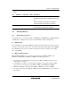
A block diagram of interrupts WUE15 to WUE8 is shown in figure 5.5.
S
R
Q
WUEMRn
WUEn input
WUEn interrupt request
Clear signal
Rising/falling-edge
selection and interrupt
enable/disable circuit
n = 15 to 8
Figure 5.5 Block Diagram of Interrupts WUE15 to WUE8