
Datasheet


Section 5 Interrupt Controller
Rev. 3.00 Sep. 28, 2009 Page 118 of 910
REJ09B0350-0300
(1) Interrupt Acceptance Control and 3-Level Control
In interrupt control modes 0 and 1, interrupt acceptance control and 3-level mask control is
performed by means of the I and UI bits in CCR and ICR (control level).
Table 5.8 shows the interrupts selected in each interrupt control mode.
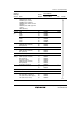
Table 5.8 Interrupts Selected in Each Interrupt Control Mode
Interrupt Mask Bits
Interrupt Control Mode I UI Selected Interrupts
0 * All interrupts (interrupt control level 1 has
priority)
0
1 * NMI and address break interrupts
0 * All interrupts (interrupt control level 1 has
priority)
1
1 0 NMI, address break, and interrupt control level 1
interrupts
1 NMI and address break interrupts
[Legend]
*: Don't care
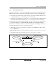
(2) Default Priority Determination
The priority is determined for the selected interrupt, and a vector number is generated.
If the same value is set for ICR, acceptance of multiple interrupts is enabled, and so only the
interrupt source with the highest priority according to the preset default priorities is selected and
has a vector number generated.
Interrupt sources with a lower priority than the accepted interrupt source are held pending.