
Datasheet


Section 8 8-Bit PWM Timer (PWMU)
Rev. 3.00 Sep. 28, 2009 Page 197 of 910
REJ09B0350-0300
Section 8 8-Bit PWM Timer (PWMU)
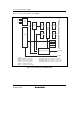
This LSI has two channels of 8-bit PWM timers, A and B (PWMU_A and PWMU_B). Each
PWMU outputs 6 PWM waveforms. Each of the PWM channels of a PWMU can operate
independently. A PWMU allows long-period PWM outputs for six channels in 8-bit single-pulse
mode and for three channels in 16-bit single-pulse mode. In addition, PWM outputs at a high
carrier frequency are available in 8-bit pulse division mode. Connecting a low-pass filter
externally to the LSI allows the PWMU to be used as an 8-bit D/A converter.
8.1 Features
• Selectable from four types of counter input clock
Selection of four internal clock signals (φ, φ/2, φ/4, and φ/8)
• Independent operation and variable cycle for each channel
Cascaded connection of two channels is possible.
Operation of channel 1 (higher order) and channel 0 (lower order) as a 16-bit single-pulse
PWM timer
Operation of channel 3 (higher order) and channel 2 (lower order) as a 16-bit single-pulse
PWM timer
Operation of channel 5 (higher order) and channel 4 (lower order) as a 16-bit single-pulse
PWM timer
• 8-bit single pulse mode
Operates at a maximum carrier frequency of 78.1 kHz (at 20 MHz operation)
Pulse output settable with a duty cycle from 0/255 to 255/255
PWM output enable/disable control, and selection of direct or inverted PWM output
• 16-bit single pulse mode
Two channels are cascade-connected for operation in this mode.
Operates at a maximum carrier frequency of 305.1 Hz (at 20 MHz operation)
Pulse output settable with a duty cycle from 0/65535 to 65535/65535
PWM output enable/disable control, and selection of direct or inverted PWM output
• 8-bit pulse division mode
Operable at a maximum carrier frequency of 1.25 MHz (at 20 MHz operation)
Pulse output settable with a duty cycle from 0/16 to 15/16
PWM output enable/disable control, and selection of direct or inverted PWM output