
Datasheet


Section 9 14-Bit PWM Timer (PWMX)
Rev. 3.00 Sep. 28, 2009 Page 224 of 910
REJ09B0350-0300
9.3.3 PWMX (D/A) Control Register (DACR)
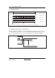
DACR enables the PWM outputs, and selects the output phase and operating speed.
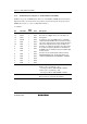
Bit Bit Name
Initial
Value
R/W Description
7 ⎯ 0 R/W` Reserved
The initial value should not be changed.
6 PWME 0 R/W PWMX Enable
Starts or stops the PWM D/A counter (DACNT).
0: DACNT operates as a 14-bit up-counter
1: DACNT halts at H′0003
5
4
⎯
⎯
1
1
R
R
Reserved
Always read as 1 and cannot be modified.
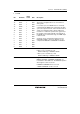
3 OEB 0 R/W Output Enable B
Enables or disables output on PWMX (D/A) channel B.
0: PWMX (D/A) channel B output (at the PWX1 output
pin) is disabled
1: PWMX (D/A) channel B output (at the PWX1 output
pin) is enabled
2 OEA 0 R/W Output Enable A
Enables or disables output on PWMX (D/A) channel A.
0: PWMX (D/A) channel A output (at the PWX0 output
pin) is disabled
1: PWMX (D/A) channel A output (at the PWX0 output
pin) is enabled
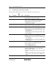
1 OS 0 R/W Output Select
Selects the phase of the PWMX (D/A) output.
0: Direct PWMX (D/A) output
1: Inverted PWMX (D/A) output
0 CKS 0 R/W Clock Select
Selects the PWMX (D/A) resolution. Eight kinds of
resolution can be selected.
0: Operates at resolution (T) = system clock cycle time
(t
cyc
)
1: Operates at resolution (T) = system clock cycle time
(t
cyc
) × 2, × 64, × 128, × 256, × 1024, × 4096, and ×
16384.