
Datasheet


Section 12 16-Bit Duty Period Measurement Timer (TDP)
Rev. 3.00 Sep. 28, 2009 Page 341 of 910
REJ09B0350-0300
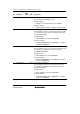
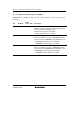
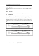
12.3.10 TDP Control Register 2 (TDPCR2)
TDPCR2 selects cycle measurement mode and controls the TDPMCI input polarity.
Bit Bit Name
Initial
Value
R/W Description
7 PMMS 0 R/W Cycle Measurement Mode Select
Selects whether to use the TDPMCI signal in cycle
measurement mode.
0: The TDPMCI signal is not used (cycle measurement is
always performed).
1: The TDPMCI signal is used (cycle measurement is
performed only while the TDPMCI signal is high).
Note: Change this bit when CST = 0 and TDPMDS = 0.
6 MCICTL 0 R/W TDPMCI Input Polarity Inversion
0: TDPMCI input is used directly
1: TDPMCI input is inverted for use
Note: Change this bit when CST = 0 and TDPMDS = 0.
5 to 1 ⎯ All 0 R/W Reserved
The initial value should not be changed.
0 ⎯ 0 R Reserved
This bit is always read as 0 and cannot be modified.