
Datasheet


Section 12 16-Bit Duty Period Measurement Timer (TDP)
Rev. 3.00 Sep. 28, 2009 Page 347 of 910
REJ09B0350-0300
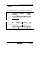
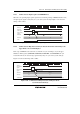
(2) Measuring a Cycle
In cycle measurement mode, one cycle of the TDP input waveform forms one measurement cycle.
Start by setting TDPMDS = 0 and CST = 0, which clears TDPCNT to H'0000. Next, set the upper
limit and lower limit values of the measurement pulse width in TDPWDMX and TDPWDMN, and
set the upper limit and lower limit values of the measurement cycle in the TDPPDMX and
TDPPDMN. Finally, place the TDP in cycle measurement mode by setting the TDPMDS bit in
TDPCR1 to 1. TDPCNT will count up cycles of the selected clock. When the first edge (either
rising or falling, as selected by the POCTL bit in TDPCR1) of the measurement cycle is detected,
TDPCNT is automatically cleared to H'0000. When the second edge is detected, the value in
TDPCNT is transferred to TDPICR. At this time, the value in TDPICR is compared with the
values in TDPWDMX and TDPWDMN. If TDPIR is greater than TDPWDMX or less than
TDPWDMN, the TWDMXOVF or TWDMNUDF flag, respectively, in TDPCSR is set to 1.
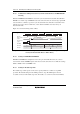
When the third edge is detected, the value in TDPCNT is transferred to TDPICR. At this time, the
value in TDPICR is compared with the values in TDPPDMX and TDPPDMN. If TDPICR is
greater than TDPPDMX or less than TDPPDMN, the TPDMXOVF or TPDMNUDF flag,
respectively, in TDPCSR is set to 1. Generation of the corresponding interrupt request is enabled
by the setting in TDPIER. Also, when the third edge is detected, TDPCNT is cleared to H'0000,
and the next round of measurement starts.
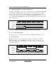
When the CPSPE bit in TDPCR1 is cleared to 0, the next round of cycle measurement will start
regardless of whether any of these flags is set to 1.
If any of these flags is set to 1 while the CPSPE bit in TDPCR1 is set to 1, counting up by
TDPCNT stops and cycle measurement also stops. Subsequently clearing the corresponding flag
to 0 automatically clears TDPCNT to H'0000, and counting up for cycle measurement is restarted.