
Datasheet


Section 12 16-Bit Duty Period Measurement Timer (TDP)
Rev. 3.00 Sep. 28, 2009 Page 353 of 910
REJ09B0350-0300
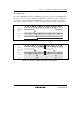
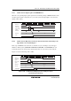
12.6.3 Conflict between Input Capture and TDPICR Read
When the corresponding input capture signal is detected during reading of TDPICR in timer mode,
the input capture signal is delayed by one cycle of the system clock (φ). Figure 12.15 shows the
timing of this conflict.
φ
TDPCYI
TDPICR
read signal
TDPICR
ICPF
Input capture
signal
N + 2N + 1N Capture occursN - 1
NM
TDPCNT
Figure 12.15 Conflict between Input Capture and TDPICR Read
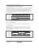
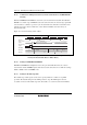
12.6.4 Conflict between Edge Detection in Cycle Measurement Mode and Writing to the
Upper Limit or Lower Limit Register
If the edge of TDPCYI is detected in the second half of a cycle of writing to any of the upper
limit/lower limit registers (TDPPDMX, TDPPDMN, TDPWDMX, and TDPWDMN) in cycle
measurement mode, the detected edge signal is delayed by one cycle of the system clock (φ).
Figure 12.16 shows the timing of this conflict.
TDPICR > TDPPDMX (Cycle upper limit exceeded)
Capture occurs
φ
TDPCYI
Internal write
signal
TDPICR
TPDMXOVF
Input capture
signal
NM
H'0000N
TDPCNT
Figure 12.16 Conflict between Edge Detection and Register Write
(Cycle Measurement Mode)