
Datasheet

Section 13 8-Bit Timer (TMR)
Rev. 3.00 Sep. 28, 2009 Page 366 of 910
REJ09B0350-0300
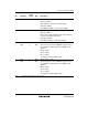
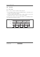
13.3.5 Timer Control/Status Register (TCSR)
TCSR indicates the status flags and controls compare-match output.
• TCSR_0
Bit Bit Name
Initial
Value
R/W Description
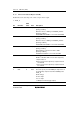
7 CMFB 0 R/(W)* Compare-Match Flag B
[Setting condition]
When the values of TCNT_0 and TCORB_0 match
[Clearing condition]
Read CMFB when CMFB = 1, then write 0 in CMFB
6 CMFA 0 R/(W)* Compare-Match Flag A
[Setting condition]
When the values of TCNT_0 and TCORA_0 match
[Clearing condition]
Read CMFA when CMFA = 1, then write 0 in CMFA
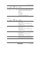
5 OVF 0 R/(W)* Timer Overflow Flag
[Setting condition]
When TCNT_0 overflows from H'FF to H'00
[Clearing condition]
Read OVF when OVF = 1, then write 0 in OVF
4 ADTE 0 R/W A/D Trigger Enable
Enables or disables A/D converter start requests by
compare-match A.
0: A/D converter start requests by compare-match A
are disabled
1: A/D converter start requests by compare-match A
are enabled
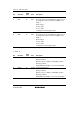
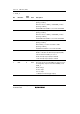
3
2
OS3
OS2
0
0
R/W
R/W
Output Select 3 and 2
These bits specify how the TMO0 pin output level is to
be changed by compare-match B of TCORB_0 and
TCNT_0.
00: No change
01: 0 is output
10: 1 is output
11: Output is inverted (toggle output)