
Datasheet

Section 15 Serial Communication Interface (SCI)
Rev. 3.00 Sep. 28, 2009 Page 406 of 910
REJ09B0350-0300
15.3.5 Serial Mode Register (SMR)
SMR is used to set the SCI's serial transfer format and select the baud rate generator clock source.
Some bits in SMR have different functions in normal mode and smart card interface mode. The
CPU can always read SMR. The CPU can write to SMR only at the initial settings; do not have the
CPU write to SMR in transmission, reception, and simultaneous data transmission and reception.
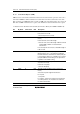
• Bit Functions in Normal Serial Communication Interface Mode (when SMIF in SCMR = 0)
Bit Bit Name Initial Value R/W Description
7 C/A 0 R/W Communication Mode
0: Asynchronous mode
1: Clocked synchronous mode
6 CHR 0 R/W Character Length (enabled only in asynchronous
mode)
0: Selects 8 bits as the data length.
1: Selects 7 bits as the data length. LSB-first is fixed
and the MSB of TDR is not transmitted in
transmission.
In clocked synchronous mode, a fixed data length of
8 bits is used.
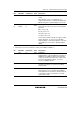
5 PE 0 R/W Parity Enable (enabled only in asynchronous mode)
When this bit is set to 1, the parity bit is added to
transmit data before transmission, and the parity bit
is checked in reception. For a multiprocessor format,
parity bit addition and checking are not performed
regardless of the PE bit setting.
4 O/E 0 R/W Parity Mode (enabled only when the PE bit is 1 in
asynchronous mode)
0: Selects even parity.
1: Selects odd parity.
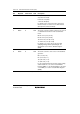
3 STOP 0 R/W Stop Bit Length (enabled only in asynchronous
mode)
Selects the stop bit length in transmission.
0: 1 stop bit
1: 2 stop bits
In reception, only the first stop bit is checked. If the
second stop bit is 0, it is treated as the start bit of
the next transmit frame.