
Datasheet


Section 15 Serial Communication Interface (SCI)
Rev. 3.00 Sep. 28, 2009 Page 455 of 910
REJ09B0350-0300
15.7.7 Serial Data Reception (Except in Block Transfer Mode)
Data reception in smart card interface mode is identical to that in normal serial communication
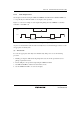
interface mode. Figure 15.29 shows the data re-transfer operation during reception.
1. If a parity error is detected in receive data, the PER bit in SSR is set to 1. Here, an ERI
interrupt request is generated if the RIE bit in SCR is set to 1. Clear the PER bit to 0 before the
next parity bit is sampled.
2. For the frame in which a parity error is detected, the RDRF bit in SSR is not set to 1.
3. If no parity error is detected, the PER bit in SSR is not set to 1. In this case, data is determined
to have been received successfully, and the RDRF bit in SSR is set to 1. Here, an RXI interrupt
request is generated if the RIE bit in SCR is set.
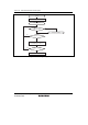
Figure 15.30 shows a sample flowchart for reception. In reception, setting the RIE bit to 1 allows
an RXI interrupt request to be generated when the RDRF flag is set to 1. If an error occurs during
reception, i.e., either the ORER or PER flag is set to 1, a transmit/receive error interrupt (ERI)
request is generated and the error flag must be cleared. Even if a parity error occurs and PER is set
to 1 in reception, receive data is transferred to RDR, thus allowing the data to be read.
Note: For operations in block transfer mode, see section 15.4, Operation in Asynchronous Mode.
D0 D1 D2 D3 D4 D5 D6 D7 Dp DE Ds D0 D1 D2 D3 D4 D5 D6 D7 Dp
(DE)
Ds D0 D1 D2 D3 D4Ds
(n + 1) th
transfer frame
Retransfer frame
n th transfer frame
RDRF
[1]
PER
[2]
[3]
[3]
Figure 15.29 Data Re-transfer Operation in SCI Reception Mode