
Datasheet


Section 16 Serial Communication Interface with FIFO (SCIF)
Rev. 3.00 Sep. 28, 2009 Page 493 of 910
REJ09B0350-0300
16.4.4 Data Transmission/Reception with Flow Control
The following shows examples of data transmission/reception for flow control using CTS and
RTS.
(1) Initialization
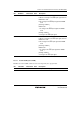
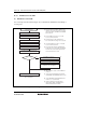
Figure 16.6 shows an example of the initialization flowchart.
Start initialization
(Transmission/reception standby flow)
Clear module stop
Set SCIFCR
Set DLAB bit in FLCR to 1
Set FDLH and FDLL
Clear DLAB bit in FLCR to 0
Set data transfer format in FLCR
Set FIFO with FFCR
Set interrupt enable bits in FIER
Set RTS bit in FMCR to 1
[1]
[2]
[3]
[4]
[5]
[6]
[7]
[8]
[1] Select an input clock with the CKSEL1 and CKSEL0
bits in SCIFCR. Set the SCIF input/output pins with
the SCIFOE1 and SCIFOE0 bits in SCIFCR.
[2] Set the DLAB bit in FLCR to 1 to enable access to
FDLL and FDLH.
[3] The initial value of FDLL and FDLH is 0. Set a value
within the range from 1 to 65535.
[4] Clear the DLAB bit in FLCR to 0 to disable access to
FDLL and FDLH.
[5] Select parity with the EPS and PEN bits in FLCR, and
set the stop bit with the STOP bit in FLCR. Then, set
the data length with the CLS1 and CLS0 bits in FLCR.
[6] Set the FIFOE bit in FFCR to 1 to enable the FIFO.
Set the receive FIFO trigger level with the RCVRTRIG1
and RCVRTRIG0 bits in FFCR. Select the best trigger
level to prevent an overflow of the receive FIFO.
[7] Set the EDSSI and ERBFI bits in FIER to 1 to enable a
modem status interrupt and receive data ready interrupt.
[8] Set the RTS bit in FMCR to 1.
Figure 16.6 Example of Initialization Flowchart