
Datasheet


Section 17 I
2
C Bus Interface (IIC)
Rev. 3.00 Sep. 28, 2009 Page 510 of 910
REJ09B0350-0300
ICDRR and the ICDRF flag is set to 1. If ICDRR contains receive data that hasn’t been read out,
any further receive data is retained in ICDRS.
Since data are not transferred from ICDRS to ICDRR in transmit mode (TRS = 1), do not read
ICDRR in transmit mode (excluding the case where final receive data is read out in the
recommended operation flow of master receive mode).
If the number of bits in a frame, excluding the acknowledge bit, is less than eight, transmit data
and receive data are stored differently. Transmit data should be written justified toward the MSB
side when MLS = 0 in ICMR, and toward the LSB side when MLS = 1. Receive data bits should
be read from the LSB side when MLS = 0, and from the MSB side when MLS = 1.
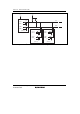
ICDR can be written to and read from only when the ICE bit is set to 1 in ICCR. The initial value
of ICDR is undefined.
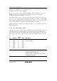
17.3.2 Slave Address Register (SAR)
SAR sets the slave address and selects the communication format. If the LSI is in slave mode with
the I
2
C bus format selected, when the FS bit is set to 0 and the upper 7 bits of SAR match the
upper 7 bits of the first frame received after a start condition, the LSI operates as the slave device
specified by the master device. SAR can be accessed only when the ICE bit in ICCR is cleared to
0.
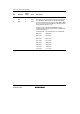
Bit Bit Name
Initial
Value
R/W Description
7
6
5
4
3
2
1
SVA6
SVA5
SVA4
SVA3
SVA2
SVA1
SVA0
0
0
0
0
0
0
0
R/W
R/W
R/W
R/W
R/W
R/W
R/W
Slave Address 6 to 0
Set a slave address.
0 FS 0 R/W Format Select
Selects the communication format together with the
FSX bit in SARX. See table 17.3.
This bit should be set to 0 when general call address
recognition is performed.