
Datasheet


Section 17 I
2
C Bus Interface (IIC)
Rev. 3.00 Sep. 28, 2009 Page 556 of 910
REJ09B0350-0300
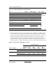
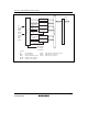
Table 17.9 I
2
C Bus Timing (SCL and SDA Outputs)
Item Symbol Output Timing Unit Notes
SCL output cycle time t
SCLO
28t
cyc
to 256t
cyc
ns
SCL output high pulse width t
SCLHO
0.5t
SCLO
ns
SCL output low pulse width t
SCLLO
0.5t
SCLO
ns
SDA output bus free time t
BUFO
0.5t
SCLO
– 1t
cyc
ns
Start condition output hold time t
STAHO
0.5t
SCLO
– 1t
cyc
ns
Retransmission start condition output
setup time
t
STASO
1t
SCLO
ns
Stop condition output setup time t
STOSO
0.5t
SCLO
+ 2t
cyc
ns
Data output setup time (master) 1t
SCLLO
– 3t
cyc
Data output setup time (slave)
t
SDASO
1t
SCLL
– (6t
cyc
or
12t
cyc
*)
ns
See figure
26.23 (for
reference)
Data output hold time t
SDAHO
3t
cyc
ns
Note: * 6t
cyc
when IICX is 0, 12t
cyc
when 1.
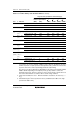
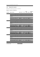
4. The I
2
C bus interface specification for the SCL rise time t
sr
is 1000 ns or less (300 ns for high-
speed mode). In master mode, the I
2
C bus interface monitors the SCL line and synchronizes
one bit at a time during communication. If t
sr
(the time for SCL to go from low to V
IH
) exceeds
the time determined by the input clock of the I
2
C bus interface, the high period of SCL is
extended. The SCL rise time is determined by the pull-up resistance and load capacitance of
the SCL line. To insure proper operation at the set transfer rate, adjust the pull-up resistance
and load capacitance so that the SCL rise time does not exceed the values given in table 17.10.
Table 17.10 Permissible SCL Rise Time (t
sr
) Values
Time Indication [ns]
IICX t
cyc
Indication
I
2
C Bus
Specification
(Max.)
φ =
8 MHz
φ =
10 MHz
φ =
16 MHz
φ =
20 MHz
Standard mode 1000 937 750 468 375 0 7.5 t
cyc
High-speed mode 300 300 300 300 300
1 17.5 t
cyc
Standard mode 1000 1000 1000 1000 875
High-speed mode 300 300 300 300 300