
Datasheet


Section 19 LPC Interface (LPC)
Rev. 3.00 Sep. 28, 2009 Page 612 of 910
REJ09B0350-0300
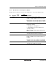
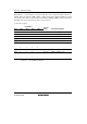
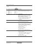
• Host select register
I/O Address
Bits 5 to 3 Bit 2 Bits 1 and 0
Transfer
Cycle Host Select Register
Bits 15 to 3 in LADR4 0 Bits 1 and 0 in LADR4 I/O write IDR4 write (data)
Bits 15 to 3 in LADR4 1 Bits 1 and 0 in LADR4 I/O write IDR4 write (command)
Bits 15 to 3 in LADR4 0 Bits 1 and 0 in LADR4 I/O read ODR4 read
Bits 15 to 3 in LADR4 1 Bits 1 and 0 in LADR4 I/O read STR4 read
Note: * When channel 4 is used, the content of LADR4 must be set so that the addresses for
channels 1, 2, 3 and SCIF are different.
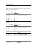
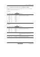
19.3.9 Input Data Registers 1 to 4 (IDR1 to IDR4)
IDR1 to IDR4 are 8-bit read-only registers for the slave (this LSI), and 8-bit write-only registers
for the host. The registers selected from the host according to the I/O address are shown in the
following table. Data transferred in an LPC I/O write cycle is written to the selected register. The
value of bit 2 of the I/O address is latched into the C/D bit in STR, to indicate whether the written
information is a command or data. The initial values of IDR1 to IDR4 are H'00.
I/O Address
Bits 15 to 4 Bit 3 Bit 2 Bit 1 Bit 0
Transfer
Cycle Host Register Selection
Bits 15 to 4 Bit 3 0 Bit 1 Bit 0 I/O write IDRn write, C/Dn ← 0
Bits 15 to 4 Bit 3 1 Bit 1 Bit 0 I/O write IDRn write, C/Dn ← 1
n = 1 to 4
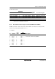
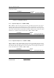
19.3.10 Output Data Registers 1 to 4 (ODR1 to ODR4)
ODR1 to ODR4 are 8-bit readable/writable registers for the slave (this LSI), and 8-bit read-only
registers for the host. The registers selected from the host according to the I/O address are shown
in the following table. In an LPC I/O read cycle, the data in the selected register is transferred to
the host. The initial values of ODR1 to ODR4 are H'00.
I/O Address
Bits 15 to 4 Bit 3 Bit 2 Bit 1 Bit 0
Transfer
Cycle Host Register Selection
Bits 15 to 4 Bit 3 0 Bit1 Bit 0 I/O read ODRn read
n = 1 to 4