
Datasheet


Section 19 LPC Interface (LPC)
Rev. 3.00 Sep. 28, 2009 Page 636 of 910
REJ09B0350-0300
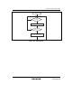
In an I/O read cycle or I/O write cycle, transfer is carried out using LAD3 to LAD0 in the
following order, in synchronization with LCLK. The host can be made to wait by sending back a
value other than B'0000 in the slave's synchronization return cycle, but with the LPC of this LSI a
value of B'0000 always returns.
If the received address matches the host address in an LPC register (IDR, ODR, STR, and TWR),
the LPC interface enters the busy state; it returns to the idle state by output of a state count 12
turnaround. Register and flag changes are made at this timing, so in the event of a transfer cycle
forced termination (abort), registers and flags are not changed.
The timing of the LFRAME, LCLK, and LAD signals is shown in figures 19.2 and 19.3.
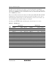
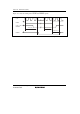
Table 19.3 LPC I/O Cycle
I/O Read Cycle I/O Write Cycle
State
Count
Contents
Drive
Source
Value
(3 to 0)
Contents
Drive
Source
Value
(3 to 0)
1 Start Host 0000 Start Host 0000
2 Cycle type/direction Host 0000 Cycle type/direction Host 0010
3 Address 1 Host Bits 15 to 12 Address 1 Host Bits 15 to 12
4 Address 2 Host Bits 11 to 8 Address 2 Host Bits 11 to 8
5 Address 3 Host Bits 7 to 4 Address 3 Host Bits 7 to 4
6 Address 4 Host Bits 3 to 0 Address 4 Host Bits 3 to 0
7 Turnaround (recovery) Host 1111 Data 1 Host Bits 3 to 0
8 Turnaround None ZZZZ Data 2 Host Bits 7 to 4
9 Synchronization Slave 0000 Turnaround (recovery) Host 1111
10 Data 1 Slave Bits 3 to 0 Turnaround None ZZZZ
11 Data 2 Slave Bits 7 to 4 Synchronization Slave 0000
12 Turnaround (recovery) Slave 1111 Turnaround (recovery) Slave 1111
13 Turnaround None ZZZZ Turnaround None ZZZZ