
Datasheet


Section 20 A/D Converter
Rev. 3.00 Sep. 28, 2009 Page 667 of 910
REJ09B0350-0300
20.5 Interrupt Source
The A/D converter generates an A/D conversion end interrupt (ADI) at the end of A/D conversion.
If the ADF bit in ADCSR has been set to 1 after A/D conversion ends and the ADIE bit is set to 1,
an ADI interrupt request is enabled.
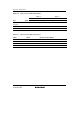
Table 20.6 A/D Converter Interrupt Source
Name Interrupt Source Interrupt Flag
ADI A/D conversion end ADF
20.6 A/D Conversion Accuracy Definitions
This LSI’s A/D conversion accuracy definitions are given below.
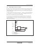
• Resolution
The number of A/D converter digital output codes
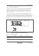
• Quantization error
The deviation inherent in the A/D converter, given by 1/2 LSB (see figure 20.3).
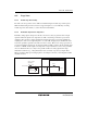
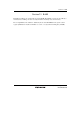
• Offset error
The deviation of the analog input voltage value from the ideal A/D conversion characteristics
when the digital output changes from the minimum voltage value B'00 0000 0000 (H'000) to
B'00 0000 0001 (H'001) (see figure 20.4).
• Full-scale error
The deviation of the analog input voltage value from the ideal A/D conversion characteristics
when the digital output changes from B'11 1111 1110 (H'3FE) to B'11 1111 1111 (H'3FF) (see
figure 20.4).
• Nonlinearity error
The error with respect to the ideal A/D conversion characteristics between the zero voltage and
the full-scale voltage. Does not include the offset error, full-scale error, or quantization error
(see figure 20.4).
• Absolute accuracy
The deviation between the digital value and the analog input value. Includes the offset error,
full-scale error, quantization error, and nonlinearity error.