
Datasheet


Section 20 A/D Converter
Rev. 3.00 Sep. 28, 2009 Page 672 of 910
REJ09B0350-0300
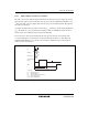
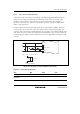
20 pF
To A/D converterAN0 to AN15
10 k
Ω
Note: Values are reference values.
Figure 20.7 Analog Input Pin Equivalent Circuit
20.7.7 Module Stop Mode Setting
When this LSI enters software standby mode with A/D conversion enabled, the analog inputs are
retained, and the analog power supply current is equal to the current as during A/D conversion. If
the analog power supply current needs to be reduced in software standby mode, clear the ADST,
TRGS1, and TRGS0 bits all to 0 to disable A/D conversion.