
Datasheet
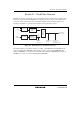


Section 23 Clock Pulse Generator
Rev. 3.00 Sep. 28, 2009 Page 760 of 910
REJ09B0350-0300
23.1 Oscillator
Clock pulses can be supplied either by connecting a crystal resonator or by providing external
clock input.
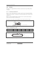
23.1.1 Connecting Crystal Resonator
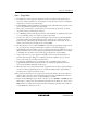
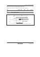
Figure 23.2 shows a typical method for connecting a crystal resonator. An appropriate damping
resistance R
d
, given in table 23.1 should be used. An AT-cut parallel-resonance crystal resonator
should be used.
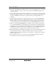
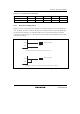
Figure 23.3 shows an equivalent circuit of a crystal resonator. A crystal resonator having the
characteristics given in table 23.2 should be used.
The frequency of the crystal resonator should be the same as that of the system clock (φ).
EXTAL
XTAL
R
d
C
L2
C
L1
C
L1
= C
L2
= 10 to 22 pF
Figure 23.2 Typical Connection to Crystal Resonator
Table 23.1 Damping Resistor Values
Frequency (MHz) 8 10 12 16 20
R
d
(Ω) 200 0 0 0 0
XTAL
C
L
AT-cut parallel-resonance crystal resonato
r
EXTAL
C
0
LR
s
Figure 23.3 Equivalent Circuit of Crystal Resonator