
Datasheet


Section 24 Power-Down Modes
Rev. 3.00 Sep. 28, 2009 Page 776 of 910
REJ09B0350-0300
24.3 Medium-Speed Mode
The operating mode changes to medium-speed mode as soon as the current bus cycle ends by the
settings of the SCK2 to SCK0 bits in SBYCR. The operating clock can be selected from φ/2, φ/4,
φ/8, φ/16, or φ/32. On-chip peripheral functions other than the bus masters and the PS2 operate on
the system clock (φ).
In medium-speed mode, a bus access is executed in the specified number of states with respect to
the bus master operating clock. For example, if φ/4 is selected as the operating clock, on-chip
memory is accessed in four states, and internal I/O registers in eight states.
A transition is made from medium-speed mode to high-speed mode at the end of the current bus
cycle by clearing all of bits SCK2 to SCK0 to 0.
If the SLEEP instruction is executed when the SSBY bit in SBYCR is 0 and the LSON bit in
LPWRCR is 0, a transition is made to sleep mode. When sleep mode is canceled by an interrupt,
medium-speed mode is restored. When the SLEEP instruction is executed with the SSBY bit set to
1, the LSON bit in LPWRCR set to 0, and the PSS bit in TCSR (WDT_1) set to 0, operation shifts
to software standby mode. When software standby mode is canceled by an external interrupt,
medium-speed mode is restored.
When the RES pin is driven low and medium-speed mode is cancelled, operation shifts to the reset
state. The same applies to a reset caused by an overflow of the watchdog timer.
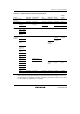
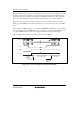
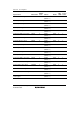
Figure 24.2 shows the timing of medium-speed mode.
peripheral module
clock
φ,
SBYCR SBYCR
Bus master clock
Internal address bus
Medium-speed mode
Internal write signal
Figure 24.2 Timing of Medium-Speed Mode