
Datasheet


Section 24 Power-Down Modes
Rev. 3.00 Sep. 28, 2009 Page 778 of 910
REJ09B0350-0300
When the RES pin is driven low, the clock pulse generator starts oscillation. Simultaneously with
the start of system clock oscillation, the system clock is supplied to the entire LSI. Note that the
RES pin must be held low until clock oscillation is stabilized. If the RES pin is driven high after
the clock oscillation stabilization time has elapsed, the CPU starts reset exception handling.
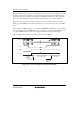
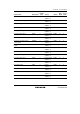
Figure 24.2 shows an example in which a transition is made to software standby mode at the
falling edge of the NMI pin, and software standby mode is cleared at the rising edge of the NMI
pin.
In this example, an NMI interrupt is accepted with the NMIEG bit in SYSCR cleared to 0 (falling
edge specification), then the NMIEG bit is set to 1 (rising edge specification), the SSBY bit is set
to 1, and a SLEEP instruction is executed, causing a transition to software standby mode.
Software standby mode is then cleared at the rising edge of the NMI pin.
Oscillator
φ
NMI exception
handling
NMIEG = 1
SSBY = 1
SLEEP instruction
Software standby mode
(power-down mode)
Oscillation
stabilization
time t
OSC2
NMI exception
handling
NMI
NMIEG
SSBY
Figure 24.3 Software Standby Mode Application Example