
Datasheet


Section 7 Data Transfer Controller (DTC)
Rev. 3.00 Mar 21, 2006 page 145 of 788
REJ09B0300-0300
Section 7 Data Transfer Controller (DTC)
This LSI includes a data transfer controller (DTC). The DTC can be activated by an interrupt or
software, to transfer data.
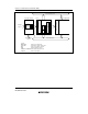
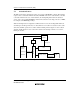
Figure 7.1 shows a block diagram of the DTC. The DTC's register information is stored in the on-
chip RAM. When the DTC is used, the RAME bit in SYSCR must be set to 1. A 32-bit bus
connects the DTC to addresses H'(FF)EC00 to H'(FF)EFFF in on-chip RAM (1 kbyte), enabling
32-bit/1-state reading and writing of the DTC register information.
7.1 Features
• Transfer is possible over any number of channels
• Three transfer modes
Normal, repeat, and block transfer modes are available.
• One activation source can trigger a number of data transfers (chain transfer)
• Direct specification of 16-Mbyte address space is possible
• Activation by software is possible
• Transfer can be set in byte or word units
• A CPU interrupt can be requested for the interrupt that activated the DTC
• Module stop mode can be set
DTCH80AA_000020020700