
Datasheet

Section 10 14-Bit PWM Timer (PWMX)
Rev. 3.00 Mar 21, 2006 page 243 of 788
REJ09B0300-0300
Section 10 14-Bit PWM Timer (PWMX)
This LSI has an on-chip 14-bit pulse-width modulator (PWM) timer with two output channels. It
can be connected to an external low-pass filter to operate as a 14-bit D/A converter.
10.1 Features
• Division of pulse into multiple base cycles to reduce ripple
• Two resolution settings
The resolution can be set equal to one or two system clock cycles.
• Two base cycle settings
The base cycle can be set equal to T × 64 or T × 256, where T is the resolution.
• Four operating speeds
• Four operation clocks (by combination of two resolution settings and two base cycle settings)
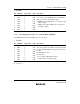
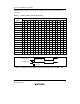
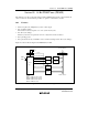
Figure 10.1 shows a block diagram of the PWM (D/A) module.
Select clock
Bus interface
Clock
Internal data bus
Comparator A
Comparator B
DADRA
DADRB
PWX1
Internal clock
φ
φ/2
PWX0
Fine–adjustment pulse addition
Fine–adjustment pulse addition
Legend:
DACR
DADRA
DADRB
DACNT
: PWM D/A control register
: PWM D/A data register A
: PWM D/A data register B
: PWM D/A counter
DACNT
DACR
Control
logic
Base cycle compare match A
Base cycle compare match B
Base cycle overflow
Module data bus
Figure 10.1 PWM (D/A) Block Diagram
PWM1411A_010020020700