
Datasheet

Section 12 8-Bit Timer (TMR)
Rev. 3.00 Mar 21, 2006 page 306 of 788
REJ09B0300-0300
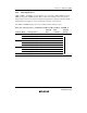
Counter Clear Specification:
• If the CCLR1 and CCLR0 bits in TCR_0 have been set for counter clear at compare-match, the
16-bit counter (TCNT_0 and TCNT_1 together) is cleared when a 16-bit compare-match
occurs. The 16-bit counter (TCNT_0 and TCNT_1 together) is also cleared when counter clear
by the TMI0 pin has been set.
• The settings of the CCLR1 and CCLR0 bits in TCR_1 are ignored. The lower 8 bits cannot be
cleared independently.
Pin Output:
• Control of output from the TMO0 pin by bits OS3 to OS0 in TCSR_0 is in accordance with the
16-bit compare-match conditions.
• Control of output from the TMO1 pin by bits OS3 to OS0 in TCSR_1 is in accordance with the
lower 8-bit compare-match conditions.
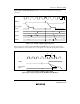
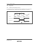
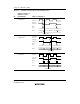
12.6.2 Compare-Match Count Mode
When bits CKS2 to CKS0 in TCR_1 are B'100, TCNT_1 counts the occurrence of compare-match
A for channel 0. Channels 0 and 1 are controlled independently. Conditions such as setting of the
CMF flag, generation of interrupts, output from the TMO pin, and counter clearing are in
accordance with the settings for each channel.
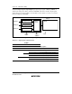
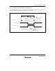
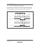
12.7 Input Capture Operation
TMR_X has input capture registers (TICR, TICRR and TICRF). A narrow pulse width can be
measured with TICRR and TICRF, using a single capture operation controlled by the ICST bit in
TCONRI of the timer connection. If the falling edge of TMRIX is detected after its rising edge has
been detected while the ICST bit is set to 1, the value of TCNT at that time is transferred to both
TICRR and TICRF, and the ICST bit is cleared to 0.
The input signal to TMRIX can be switched by the setting of the other bits in TCONRI.