
Datasheet

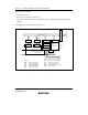


Section 15 Serial Communication Interface (SCI and IrDA)
Rev. 3.00 Mar 21, 2006 page 364 of 788
REJ09B0300-0300
Bit Bit Name Initial Value R/W Description
2 MP 0 R/W Multiprocessor Mode (enabled only in asynchronous
mode)
When this bit is set to 1, the multiprocessor
communication function is enabled. The PE bit and
O/E bit settings are invalid in multiprocessor mode.
1
0
CKS1
CKS0
0
0
R/W
R/W
Clock Select 1,0
These bits select the clock source for the on-chip baud
rate generator.
00: φ clock (n = 0)
01: φ/4 clock (n = 1)
10: φ/16 clock (n = 2)
11: φ/64 clock (n = 3)
For the relation between the bit rate register setting
and the baud rate, see section 15.3.9, Bit Rate
Register (BRR). n is the decimal display of the value of
n in BRR.
15.3.6 Serial Control Register (SCR)
SCR is a register that performs enabling or disabling of SCI transfer operations and interrupt
requests, and selection of the transfer clock source. For details on interrupt requests, refer to
section 15.8, Interrupt Sources.
Bit Bit Name Initial Value R/W Description
7 TIE 0 R/W Transmit Interrupt Enable
When this bit is set to 1, a TXI interrupt request is
enabled.
6 RIE 0 R/W Receive Interrupt Enable
When this bit is set to 1, RXI and ERI interrupt requests
are enabled.
5 TE 0 R/W Transmit Enable
When this bit is set to 1, transmission is enabled.
4 RE 0 R/W Receive Enable
When this bit is set to 1, reception is enabled.