
Datasheet


Section 18 Host Interface X-Bus Interface (XBS)
Rev. 3.00 Mar 21, 2006 page 525 of 788
REJ09B0300-0300
18.5 Interrupt Sources
18.5.1 IBF1, IBF2, IBF3, and IBF4
The host interface can issue four interrupt requests to the slave processor: IBF1 to IBF4. They are
input buffer full interrupts for input data registers IDR_1 to IDR_4 respectively. Each interrupt is
enabled when the corresponding enable bit is set.
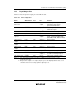
Table 18.8 Input Buffer Full Interrupts
Interrupt Description
IBF1 Requested when IBFIE1 is set to 1 and IDR_1 is full
IBF2 Requested when IBFIE2 is set to 1 and IDR_2 is full
IBF3 Requested when IBFIE3 is set to 1 and IDR_3 is full
IBF4 Requested when IBFIE4 is set to 1 and IDR_4 is full
18.5.2 HIRQ11, HIRQ1, HIRQ12, HIRQ3, and HIRQ4
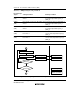
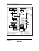
Bits P45DR to P43DR in the port 4 data register (P4DR) and bits PB1ODR and PB0ODR in the
port B data register (PBODR) can be used as host interrupt request latches. When they are used as
host interrupt request output, set each bit in the data direction register (DDR) of the pin to 1.
The corresponding bits in P4DR are cleared to 0 by the host processor’s read signal (IOR). If CS1
and HA0 are low, when IOR goes low and the host reads ODR_1, HIRQ1 and HIRQ12 are cleared
to 0. If CS2 and HA0 are low, when IOR goes low and the host reads ODR_2, HIRQ11 is cleared
to 0. The corresponding bit in PBODR is cleared to 0 by the host’s read signal (IOR). If CS3 and
HA0 are low, when IOR goes low and the host reads ODR_3, HIRQ3 is cleared to 0. If CS4 and
HA0 are low, when IOR goes low and the host reads ODR_4, HIRQ4 is cleared to 0. To generate
a host interrupt request, normally on-chip firmware writes 1 in the corresponding bit. In processing
the interrupt, the host’s interrupt handling routine reads the output data register (ODR_1, ODR_2,
ODR_3, or ODR_4) and this clears the host interrupt latch to 0.
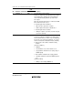
Table 18.9 indicates how these bits are set and cleared. Figure 18.3 shows the processing in
flowchart form.