
Datasheet

Section 7 Data Transfer Controller (DTC)
Rev. 4.00 Sep 27, 2006 page 193 of 1130
REJ09B0327-0400
7.3.3 DTC Vector Table
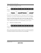
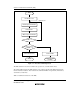
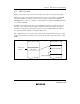
Figure 7.4 shows the correspondence between DTC vector addresses and register information.
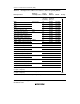
Table 7.4 shows the correspondence between activation sources, vector addresses, and DTCER
bits. When the DTC is activated by software, the vector address is obtained from: H'0400 +
DTVECR[6:0] << 1 (where << 1 indicates a 1-bit left shift). For example, if DTVECR is H'10, the
vector address is H'0420.
The DTC reads the start address of the register information from the vector address set for each
activation source, and then reads the register information from that start address. The register
information can be placed at predetermined addresses in the on-chip RAM. The start address of
the register information should be an integral multiple of four.
The configuration of the vector address is the same in both normal and advanced modes, a 2-byte
unit being used in both cases. These two bytes specify the lower bits of the address in the on-chip
RAM.
Register information
start address
Register information
Chain transfer
DTC vector
address
Figure 7.4 Correspondence between DTC Vector Address and Register Information