
Datasheet

Section 12 8-Bit Timers
Rev. 4.00 Sep 27, 2006 page 350 of 1130
REJ09B0327-0400
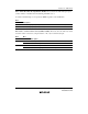
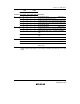
Bits 2 to 0—Clock Select 2 to 0 (CKS2 to CKS0): These bits select whether the clock input to
TCNT is an internal or external clock.
The input clock can be selected from either six or three clocks, all divided from the system clock
(φ). The falling edge of the selected internal clock triggers the count.
When use of an external clock is selected, three types of count can be selected: at the rising edge,
the falling edge, and both rising and falling edges.
Some functions differ between channel 0 and channel 1, because of the cascading function.
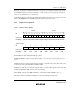
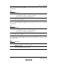
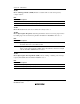
TCR STCR
Bit 2 Bit 1 Bit 0 Bit 1 Bit 0
Channel CKS2 CKS1 CKS0 ICKS1 ICKS0 Description
0 0 0 0 — — Clock input disabled (Initial value)
001—0 φ/8 internal clock source, counted on the falling edge
001—1 φ/2 internal clock source, counted on the falling edge
010—0 φ/64 internal clock source, counted on the falling
edge
010—1 φ/32 internal clock source, counted on the falling
edge
011—0 φ/1024 internal clock source, counted on the falling
edge
011—1 φ/256 internal clock source, counted on the falling
edge
1 0 0 — — Counted on TCNT1 overflow signal
*
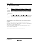
1 0 0 0 — — Clock input disabled (Initial value)
0010 —φ/8 internal clock source, counted on the falling edge
0011 —φ/2 internal clock source, counted on the falling edge
0100 —φ/64 internal clock source, counted on the falling
edge
0101 —φ/128 internal clock source, counted on the falling
edge
0110 —φ/1024 internal clock source, counted on the falling
edge
0111 —φ/2048 internal clock source, counted on the falling
edge
1 0 0 — — Counted on TCNT0 compare-match A
*