
Datasheet


Section 16 I
2
C Bus Interface [Option]
Rev. 4.00 Sep 27, 2006 page 523 of 1130
REJ09B0327-0400
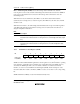
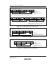
SDA
SCL
S
1-7
SLA
8
R/W
9
A
1-7
DATA
89 1-7 89
A DATA PA/A
Figure 16.6 I
2
C Bus Timing
Table 16.4 I
2
C Bus Data Format Symbols
Legend
S Start condition. The master device drives SDA from high to low while SCL is high
SLA Slave address, by which the master device selects a slave device
R/W Indicates the direction of data transfer: from the slave device to the master device
when R/W is 1, or from the master device to the slave device when R/W is 0
A Acknowledge. The receiving device (the slave in master transmit mode, or the master
in master receive mode) drives SDA low to acknowledge a transfer
DATA Transferred data. The bit length is set by bits BC2 to BC0 in ICMR. The MSB-first or
LSB-first format is selected by bit MLS in ICMR
P Stop condition. The master device drives SDA from low to high while SCL is high
16.3.2 Master Transmit Operation
In I
2
C bus format master transmit mode, the master device outputs the transmit clock and transmit
data, and the slave device returns an acknowledge signal.
The transmission procedure and operations by which data is sequentially transmitted in
synchronization with ICDR write operations, are described below.
(1) Set the ICE bit in ICCR to l. Set bits MLS, WAIT, and CKS2 to CKS0 in ICMR, and bit IICX
in STCR, according to the operation mode.
(2) Read the BBSY flag to confirm that the bus is free.
(3) Set the MST and TRS bits to 1 in ICCR to select master transmit mode.
(4) Write 1 to BBSY and 0 to SCP. This switches SDA from high to low when SCL is high, and
generates the start condition.
(5) When the start condition is generated, the IRIC and IRTR flags are set to 1. If the IEIC bit in
ICCR has been set to l, an interrupt request is sent to the CPU.