
Datasheet


Section 20 A/D Converter
Rev. 4.00 Sep 27, 2006 page 613 of 1130
REJ09B0327-0400
Section 20 A/D Converter
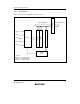
20.1 Overview
This LSI incorporate a 10-bit successive-approximations A/D converter that allows up to eight
analog input channels to be selected.
In addition to the eight analog input channels, up to 16 channels of digital input can be selected for
A/D conversion. Since the conversion precision falls when digital input is selected, digital input is
ideal for use by a comparator identifying multi-valued inputs, for example.
20.1.1 Features
A/D converter features are listed below.
• 10-bit resolution
• Eight (analog) or 16 (digital) input channels
• Settable analog conversion voltage range
The analog conversion voltage range is set using the reference power supply voltage pin
(AVref) as the analog reference voltage
• High-speed conversion
Minimum conversion time: 6.7 µs per channel (at 20-MHz operation)
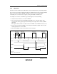
• Choice of single mode or scan mode
Single mode: Single-channel A/D conversion
Scan mode: Continuous A/D conversion on 1 to 4 channels
• Four data registers
Conversion results are held in a 16-bit data register for each channel
• Sample and hold function
• Three kinds of conversion start
Choice of software or timer conversion start trigger (8-bit timer), or ADTRG pin
• A/D conversion end interrupt generation
An A/D conversion end interrupt (ADI) request can be generated at the end of A/D
conversion