
Datasheet


Section 25 Power-Down State
Rev. 4.00 Sep 27, 2006 page 749 of 1130
REJ09B0327-0400
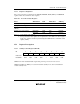
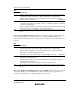
Bits 2 to 0—System Clock Select (SCK2 to SCK0): These bits select the clock for the bus
master in high-speed mode and medium-speed mode. When operating the device after a transition
to subactive mode or watch mode, bits SCK2 to SCK0 should all be cleared to 0.
Bit 2 Bit 1 Bit 0
SCK2 SCK1 SCK0 Description
0 0 0 Bus master is in high-speed mode (Initial value
)
1 Medium-speed clock is φ/2
1 0 Medium-speed clock is φ/4
1 Medium-speed clock is φ/8
1 0 0 Medium-speed clock is φ/16
1 Medium-speed clock is φ/32
1 ——
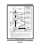
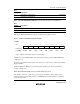
25.2.2 Low-Power Control Register (LPWRCR)
7
DTON
0
R/W
6
LSON
0
R/W
5
NESEL
0
R/W
4
EXCLE
0
R/W
3
—
0
—
0
—
0
—
2
—
0
—
1
—
0
—
Bit
Initial value
Read/Write
LPWRCR is an 8-bit readable/writable register that performs power-down mode control.
LPWRCR is initialized to H'00 by a reset and in hardware standby mode. It is not initialized in
software standby mode.
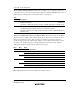
Bit 7—Direct-Transfer On Flag (DTON): Specifies whether a direct transition is made between
high-speed mode, medium-speed mode, and subactive mode when making a power-down
transition by executing a SLEEP instruction. The operating mode to which the transition is made
after SLEEP instruction execution is determined by a combination of other control bits.