
Datasheet

Appendix A Instruction Set
Rev. 4.00 Sep 27, 2006 page 961 of 1130
REJ09B0327-0400
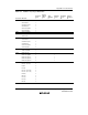
A.4 Number of States Required for Execution
The tables in this section can be used to calculate the number of states required for instruction
execution by the H8S/2000 CPU. Table A.5 shows the number of instruction fetch, data
read/write, and other cycles occurring in each instruction, and table A.4 shows the number of
states required per cycle according to the bus size. The number of states required for execution of
an instruction can be calculated from these two tables as follows:
Number of states = I × S
I
+ J × S
J
+ K × S
K
+ L × S
L
+ M × S
M
+ N × S
N
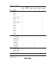
Examples of Calculation of Number of States Required for Execution
Examples: Advanced mode, stack located in external address space, on-chip supporting modules
accessed in two states with 8-bit bus width, external devices accessed in three states with one wait
state and 16-bit bus width.
1. BSET #0,@FFFFC7:8
From table A.5,
I = L = 2 and J = K = M = N = 0
From table A.4,
S
I
= 4 and S
L
= 2
Number of states = 2 × 4 + 2 × 2 = 12
2. JSR @@30
From table A.5,
I = J = K = 2 and L = M = N = 0
From table A.4,
S
I
= S
J
= S
K
= 4
Number of states = 2 × 4 + 2 × 4 + 2 × 4 = 24