
Datasheet


Section 2 CPU
Rev. 4.00 Sep 27, 2006 page 64 of 1130
REJ09B0327-0400
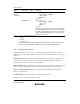
Type Instruction Size
*
1
Function
Block data
transfer
instructions
EEPMOV.B
EEPMOV.W
—
—
if R4L ≠ 0 then
Repeat @ER5+ → @ER6+
R4L–1 → R4L
Until R4L = 0
else next;
if R4 ≠ 0 then
Repeat @ER5+ → @ER6+
R4–1 → R4
Until R4 = 0
else next;
Block transfer instruction. Transfers the number of data
bytes specified by R4L or R4 from locations starting at
the address indicated by ER5 to locations starting at the
address indicated by ER6. After the transfer, the next
instruction is executed.
Notes: 1. Size refers to the operand size.
B: Byte
W: Word
L: Longword
2. Only register ER0, ER1, ER4, or ER5 should be used when using the TAS instruction.
3. Only registers ER0 to ER6 should be used when using the STM/LDM instruction.
2.6.4 Basic Instruction Formats
The CPU instructions consist of 2-byte (1-word) units. An instruction consists of an operation
field (op field), a register field (r field), an effective address extension (EA field), and a condition
field (cc).
Operation Field: Indicates the function of the instruction, the addressing mode, and the operation
to be carried out on the operand. The operation field always includes the first four bits of the
instruction. Some instructions have two operation fields.
Register Field: Specifies a general register. Address registers are specified by 3 bits, data registers
by 3 bits or 4 bits. Some instructions have two register fields. Some have no register field.
Effective Address Extension: Eight, 16, or 32 bits specifying immediate data, an absolute
address, or a displacement.
Condition Field: Specifies the branching condition of Bcc instructions.
Figure 2.12 shows examples of instruction formats.