
Datasheet

Section 3 MCU Operating Modes
Rev. 4.00 Sep 27, 2006 page 85 of 1130
REJ09B0327-0400
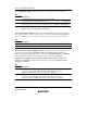
Bit 7—Expanded Mode Enable (EXPE): Sets expanded mode. In mode 1, this bit is fixed at 1
and cannot be modified. In modes 2 and 3, this bit has an initial value of 0, and can be read and
written.
Bit 7
EXPE Description
0 Single chip mode is selected
1 Expanded mode is selected
Bits 6 to 2—Reserved: These bits cannot be modified and are always read as 0.
Bits 1 and 0—Mode Select 1 and 0 (MDS1, MDS0): These bits indicate the input levels at pins
MD1 and MD0 (the current operating mode). Bits MDS1 and MDS0 correspond to MD1 and
MD0. MDS1 and MDS0 are read-only bits—they cannot be written to. The mode pin (MD1 and
MD0) input levels are latched into these bits when MDCR is read.
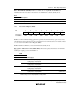
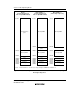
3.2.2 System Control Register (SYSCR)
7
CS2E
0
R/W
6
IOSE
0
R/W
5
INTM1
0
R
4
INTM0
0
R/W
3
XRST
1
R
0
RAME
1
R/W
2
NMIEG
0
R/W
1
HIE
0
R/W
Bit
Initial value
Read/Write
SYSCR is an 8-bit readable/writable register that performs selection of system pin functions, reset
source monitoring, interrupt control mode selection, NMI detected edge selection, supporting
module pin location selection, supporting module register access control, and RAM address space
control.
Only bits 7, 6, 3, 1, and 0 are described here. For a detailed description of these bits, refer also to
the description of the relevant modules (host interface, bus controller, watchdog timer, RAM,
etc.). For information on bits 5, 4, and 2, see section 5.2.1, System Control Register (SYSCR).
SYSCR is initialized to H'09 by a reset and in hardware standby mode. It is not initialized in
software standby mode.
Bit 7—Chip Select 2 Enable (CS2E): Specifies the location of the host interface control pin
(CS2). For details, see section 18, Host Interface. The H8S/2144 Group does not incorporate a
host interface, so do not set this bit to 1 in the H8S/2144 Group.