
Datasheet


Section 5 Interrupt Controller
Rev. 4.00 Sep 27, 2006 page 118 of 1130
REJ09B0327-0400
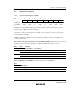
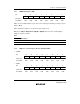
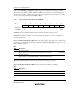
5.2.2 Interrupt Control Registers A to C (ICRA to ICRC)
7
ICR7
0
R/W
6
ICR6
0
R/W
5
ICR5
0
R/W
4
ICR4
0
R/W
3
ICR3
0
R/W
0
ICR0
0
R/W
2
ICR2
0
R/W
1
ICR1
0
R/W
Bit
Initial value
Read/Write
The ICR registers are three 8-bit readable/writable registers that set the interrupt control level for
interrupts other than NMI and address break.
The correspondence between ICR settings and interrupt sources is shown in table 5.3.
The ICR registers are initialized to H'00 by a reset and in hardware standby mode.
Bit n—Interrupt Control Level (ICRn): Sets the control level for the corresponding interrupt
source.
Bit n
ICRn Description
0 Corresponding interrupt source is control level 0 (non-priority) (Initial value)
1 Corresponding interrupt source is control level 1 (priority)
Note: n = 7 to 0
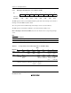
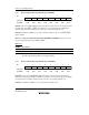
Table 5.3 Correspondence between Interrupt Sources and ICR Settings
Bits
Register76543210
ICRA IRQ0 IRQ1 IRQ2
IRQ3
IRQ4
IRQ5
IRQ6
IRQ7
DTC Watchdog
timer 0
Watchdog
timer 1
ICRB A/D
converter
Free-
running
timer
— — 8-bit
timer
channel 0
8-bit
timer
channel 1
8-bit
timer
channels
X, Y
HIF,
Keyboard
buffer
controller
ICRC SCI
channel 0
SCI
channel 1
SCI
channel 2
IIC
channel 0
(option)
IIC
channel 1
(option)
———