
Datasheet

Section 5 Interrupt Controller
Rev. 4.00 Sep 27, 2006 page 137 of 1130
REJ09B0327-0400
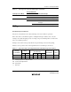
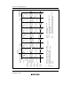
Table 5.6 Interrupts Selected in Each Interrupt Control Mode
Interrupt Mask Bits
Interrupt Control Mode I UI Selected Interrupts
00* All interrupts (control level 1 has priority)
1 * NMI and address break interrupts
10* All interrupts (control level 1 has priority)
1 0 NMI, address break and control level 1
interrupts
1 NMI, and address break interrupts
Legend:
*: Don’t care
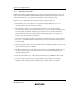
Default Priority Determination
The priority is determined for the selected interrupt, and a vector number is generated.
If the same value is set for ICR, acceptance of multiple interrupts is enabled, and so only the
interrupt source with the highest priority according to the preset default priorities is selected and
has a vector number generated.
Interrupt sources with a lower priority than the accepted interrupt source are held pending.
Table 5.7 shows operations and control signal functions in each interrupt control mode.
Table 5.7 Operations and Control Signal Functions in Each Interrupt Control Mode
Setting
Interrupt Acceptance Control
3-Level Control
Interrupt
Control Mode
INTM1 INTM0 I UI ICR
Default Priority
Determination
T
(Trace)
000
O
IM — PR
O
—
101
O
IM IM PR
O
—
Legend:
O: Interrupt operation control performed
IM: Used as interrupt mask bit
PR: Sets priority
—: Not used