
Datasheet


Section 5 Interrupt Controller
Rev. 4.00 Sep 27, 2006 page 138 of 1130
REJ09B0327-0400
5.5.2 Interrupt Control Mode 0
Enabling and disabling of IRQ interrupts and on-chip supporting module interrupts can be set by
means of the I bit in the CPU’s CCR, and ICR. Interrupts are enabled when the I bit is cleared to
0, and disabled when set to 1. Control level 1 interrupt sources have higher priority.
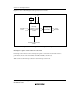
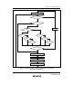
Figure 5.8 shows a flowchart of the interrupt acceptance operation in this case.
1. If an interrupt source occurs when the corresponding interrupt enable bit is set to 1, an
interrupt request is sent to the interrupt controller.
2. When interrupt requests are sent to the interrupt controller, a control level 1 interrupt,
according to the control level set in ICR, has priority for selection, and other interrupt requests
are held pending. If a number of interrupt requests with the same control level setting are
generated at the same time, the interrupt request with the highest priority according to the
priority system shown in table 5.4 is selected.
3. The I bit is then referenced. If the I bit is cleared to 0, the interrupt request is accepted. If the I
bit is set to 1, only NMI and address break interrupt are accepted, and other interrupt requests
are held pending.
4. When an interrupt request is accepted, interrupt exception handling starts after execution of the
current instruction has been completed.
5. The PC and CCR are saved to the stack area by interrupt exception handling. The PC saved on
the stack shows the address of the first instruction to be executed after returning from the
interrupt handling routine.
6. Next, the I bit in CCR is set to 1. This disables all interrupts except NMI and address break.
7. A vector address is generated for the accepted interrupt, and execution of the interrupt
handling routine starts at the address indicated by the contents of that vector address.