
Datasheet


Section 5 Interrupt Controller
Rev. 4.00 Sep 27, 2006 page 140 of 1130
REJ09B0327-0400
5.5.3 Interrupt Control Mode 1
Three-level masking is implemented for IRQ interrupts and on-chip supporting module interrupts
by means of the I and UI bits in the CPU’s CCR, and ICR.
• Control level 0 interrupt requests are enabled when the I bit is cleared to 0, and disabled when
set to 1.
• Control level 1 interrupt requests are enabled when the I bit or UI bit is cleared to 0, and
disabled when both the I bit and the UI bit are set to 1.
For example, if the interrupt enable bit for an interrupt request is set to 1, and H'20, H'00, and H'00
are set in ICRA, ICRB, and ICRC, respectively, (i.e. IRQ2 and IRQ3 interrupts are set to control
level 1 and other interrupts to control level 0), the situation is as follows:
• When I = 0, all interrupts are enabled
(Priority order: NMI > IRQ2 > IRQ3 > address break > IRQ0 > IRQ1 ...)
• When I = 1 and UI = 0, only NMI, IRQ2, IRQ3 and address break interrupts are enabled
• When I = 1 and UI = 1, only NMI and address break interrupts are enabled
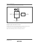
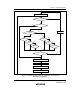
Figure 5.9 shows the state transitions in these cases.
Only NMI interrupts and
address break enabled
All interrupts enabled
Exception handling execution
or I ← 1, UI ← 1
I ← 0
I ← 1, UI ← 0
I ← 0 UI ← 0
Exception handling execution
or UI ← 1
Only NMI, IRQ2, IRQ3,
and address break
interrupts enabled
Figure 5.9 Example of State Transitions in Interrupt Control Mode 1