
Datasheet


Section 6 Bus Controller
Rev. 4.00 Sep 27, 2006 page 157 of 1130
REJ09B0327-0400
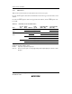
Bits 1 and 0—Wait Count 1 and 0 (WC1, WC0): These bits select the number of program wait
states when external memory space is accessed while the AST bit is set to 1.
Bit 1 Bit 0
WC1 WC0 Description
0 0 No program wait states are inserted
1 1 program wait state is inserted in external memory space accesses
1 0 2 program wait states are inserted in external memory space accesses
1 3 program wait states are inserted in external memory space accesses
(Initial value)
6.3 Overview of Bus Control
6.3.1 Bus Specifications
The external space bus specifications consist of three elements: bus width, number of access
states, and wait mode and number of program wait states.
The bus width and number of access states for on-chip memory and internal I/O registers are
fixed, and are not affected by the bus controller.
Bus Width: A bus width of 8 or 16 bits can be selected with the ABW bit.
Number of Access States: Two or three access states can be selected with the AST bit.
When 2-state access space is designated, wait insertion is disabled. The number of access states on
the burst ROM interface is determined without regard to the AST bit setting.
Wait Mode and Number of Program Wait States: When 3-state access space is designated by
the AST bit, the wait mode and the number of program wait states to be inserted automatically is
selected with WMS1, WMS0, WC1, and WC0. From 0 to 3 program wait states can be selected.
Table 6.3 shows the bus specifications for each basic bus interface area.