
Datasheet


Section 6 Bus Controller
Rev. 4.00 Sep 27, 2006 page 159 of 1130
REJ09B0327-0400
6.3.4 I/O Select Signal
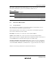
In this LSI, an I/O select signal (IOS) can be output, with the signal output going low when the
designated external space is accessed.
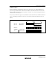
Figure 6.2 shows an example of IOS signal output timing.
φ
Address bus
IOS
T
1
T
2
T
3
Bus cycle
External address in IOS set range
Figure 6.2 IOS
IOSIOS
IOS Signal Output Timing
Enabling or disabling of IOS signal output is controlled by the setting of the IOSE bit in SYSCR.
In expanded mode, this pin operates as the AS output pin after a reset, and therefore the IOSE bit
in SYSCR must be set to 1 in order to use this pin as the IOS signal output. See section 8, I/O
Ports, for details.
The range of addresses for which the IOS signal is output can be set with bits IOS1 and IOS0 in
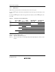
BCR. The IOS signal address ranges are shown in table 6.4.
Table 6.4 IOS
IOSIOS
IOS Signal Output Range Settings
IOS1 IOS0 IOS
IOSIOS
IOS Signal Output Range
0 0 H'(FF)F000 to H'(FF)F03F
1 H'(FF)F000 to H'(FF)F0FF
1 0 H'(FF)F000 to H'(FF)F3FF
1 H'(FF)F000 to H'(FF)FE4F
*
(Initial value)
Note: * In the H8S/2148 and H8S/2147 F-ZTAT A-mask version, the address range is from
H'(FF)F000 to H'(FF)F7FF.