
Datasheet


Section 6 Bus Controller
Rev. 4.00 Sep 27, 2006 page 171 of 1130
REJ09B0327-0400
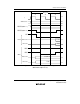
6.4.5 Wait Control
When accessing external space, the MCU can extend the bus cycle by inserting one or more wait
states (T
W
). There are three ways of inserting wait states: program wait insertion, pin wait insertion
using the WAIT pin, and a combination of the two.
Program Wait Mode: In program wait mode, the number of T
W
states specified by bits WC1 and
WC0 are always inserted between the T
2
and T
3
states when external space is accessed.
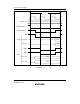
Pin Wait Mode: In pin wait mode, the number of T
W
states specified by bits WC1 and WC0 are
always inserted between the T
2
and T
3
states when external space is accessed. If the WAIT pin is
low at the fall of φ in the last T
2
or T
W
state, another T
W
state is inserted. If the WAIT pin is held
low, T
W
states are inserted until it goes high.
Pin wait mode is useful for inserting four or more wait states, or for changing the number of T
W
states for different external devices.
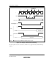
Pin Auto-Wait Mode: In pin auto-wait mode, if the WAIT pin is low at the fall of φ in the T
2
state, the number of T
W
states specified by bits WC1 and WC0 are inserted when external space is
accessed. No additional T
W
states are inserted even if the WAIT pin remains low. Pin auto-wait
mode can be used for an easy interface to low-speed memory, simply by routing the chip select
signal to the WAIT pin.
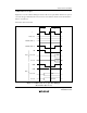
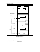
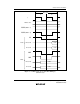
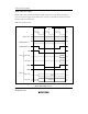
Figure 6.13 shows an example of wait state insertion timing.